UMA-Offices
The UMA-Offices dataset was collected in our facilities at the University of Málaga. It consist of 25 scenarios captured through an RGB-D sensor mounted on a robot.
If you use the dataset, please cite it as:
@INPROCEEDINGS{Ruiz-Sarmiento-KBS-2015,
             author = {Ruiz-Sarmiento, J. R. and Galindo, Cipriano and Gonz{\'{a}}lez-Jim{\'{e}}nez, Javier},
              title = {Exploiting Semantic Knowledge for Robot Object Recognition},
            journal = {Knowledge-Based Systems},
             volume = {86},
               year = {2015},
                doi = {doi:10.1016/j.knosys.2015.05.032},
              pages = {131--142},
      }

       @inproceedings{fernandez2013fast,
             title = {Fast place recognition with plane-based maps},
            author = {Fern{\'a}ndez-Moral, Eduardo and Mayol-Cuevas, W and Ar{\'e}valo, Vicente and Gonz{\'a}lez-Jim{\'e}nez, J},
         booktitle = {Robotics and Automation (ICRA), 2013 IEEE International Conference on},
             pages = {2719--2724},
              year = {2013},
      organization = {IEEE}
        }
The full dataset can be downloaded here:
- UMA-Offices dataset (11.2MB)
Please read the following sections for more information about the provided data.
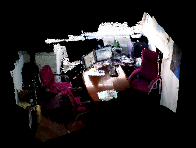
Point clouds
The dataset supplies the registered point clouds of 12 offices. These offices were visited several times, hence providing the 25 scenarios aforementioned. Some examples of these reconstructions:
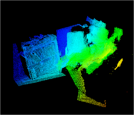
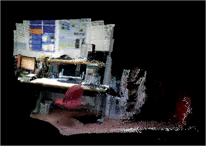
The point clouds are in the .pcd format, and include color information:
- Point clouds (11.1MB)
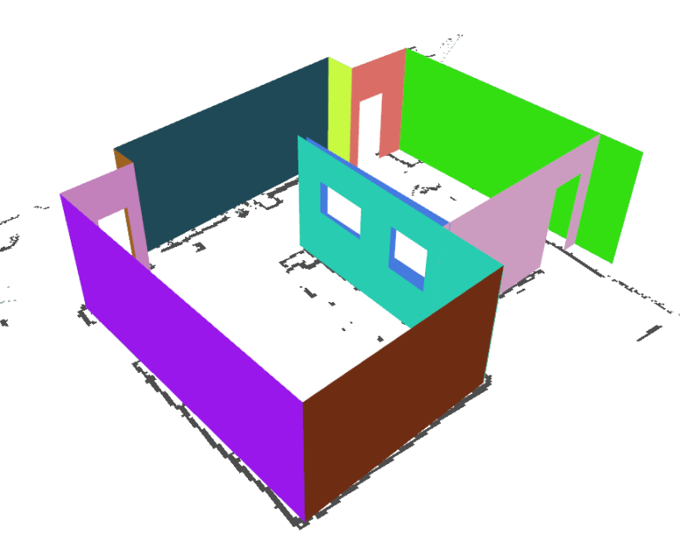
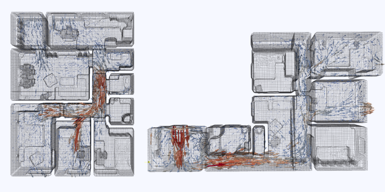
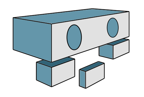
Extracted planes
The point clouds were reconstructed employing plane-based maps (PbMaps), which consist of a set of 3D planar patches described by simple geometric features (normal vector, centroid, area, etc.). The following file contains the planar patches extracted from each office and their features computed during the PbMap building, stored in .xml files:
- Extracted planes (50KB)
Processed data
The following file contains the processed data of the objects that were observed in such scenarios ready to be loaded into a Matlab workspace, but it can be easily parsed for other purposes:
- Processed data (17KB)
Concretely, the content for each scenario within this file is as follows:
%------------------------------------------------------%
% Scenario 1 Scenario ID (office_1) Office ID where the scenario was collected
%------------------------------------------------------%

tests.Y1 = [ ]; Vector containing the ground truth type of each object (see below)

tests.edges1=[ ]; NxM matrix stating the edges between nearby objects. N is the number of edges, and M is 2.

tests.relations1isOn=[ ]; Vector indicating if an object within an edge is placed ON the other object in the same edge.

tests.relations1coplanar=[ ]; Vector indicating if an object within an edge is COPLANAr with the other object in the same edge.

tests.X1=[ ]; NxM matrix providing the features computed for each object. Rows index N objects, while columns index M features.
The possible object types are:
- 1: floor
- 2: wall
- 3: table
- 4: tableSide
- 5: chairBack
- 6: chairSeat
- 7: computerScreen
- 8: laptop
- 9: PCfront
- 10: PCside
- 11: cupboardSide
And the extracted features are:
- Orientation
- Height of the centroid from the floor
- Area
- Elongationcentroid_z area elongation
Contact
Don’t hesitate to contact jotaraul@uma.es if you want additional information.